Multipath Wi-Fi bridging with transparent MPTCP proxy on LEDE
Contents
This post is outdated
The methods described in this blogpost might be outdated. I recommend to take a look into the OpenMPTCPRouter (https://www.openmptcprouter.com/) project for an up-to-date approach. If you want to reproduce the proxy described in this blogpost, please be really careful. Thanks!
Brief intro
- LEDE (Linux Embedded Development Environment) is a fork of OpenWRT the well known Linux distro for routers.
- MPTCP (MultiPath Transmission Control Protocol) is defined in RFC 6824. Designed to use multiple network interfaces (Ethernet, Wi-Fi, LTE, etc.) for a communication session.
- shadowsocks-libev is a lightweight proxy application. It has TCP redirection functionality (ss-redir module) which will be used later.
Main problem and the goal of the project
In a Wi-Fi mesh network (like Freifunk backbone) there are multiple point-to-point links between the single nodes. I’m not really into it, but secondary links might be used for failover purposes or some load balancing work between the different paths. For better resource allocation, the free capacity on the secondary links should be used if it exists. That’s where MPTCP comes in: we can build MPTCP subflows over them, and because of the smart congestion control algorithm it only uses as many bandwidth on the secondary link as many available. In this project, I will show step-by-step how You can achieve this kind of operation in real life environment. There are few things which are required for the project:
- 2 routers
- 4 Wi-Fi bridge for two point-to-point WAN Wi-Fi links (or 2 UDP cable for testing)
- LEDE with MPTCP support
- shadowsocks-libev
Operation example
- Clients are connecting to the routers. They only supporting regular TCP.
- When a client starts a TCP session, which runs through the router, we redirect it on the router to the local port if the ss-redir with an iptables rule.
- The router supports MPTCP and builds multiple subflows over the Wi-Fi WAN paths with the second router.
- On the second router ss-server reintercepts the traffic of the subflows into a recently opened regular TCP flow to the client’s original destination.
- The endpoints are enjoying the benefits of multiple WAN paths (larger bandwidth, better and faster failover).
Guide for reproducing the project
1. Get the required software environment and build the LEDE images for the routers
First, we need to download my fork of LEDE which contains the patch for MPTCP support.
|
|
Before we go ahead, let’s make sure we have the required dependencies for the built environment and install them.
|
|
Then lets prepare the build environment and get the latest package infos and patches.
|
|
In the next step, we need to turn on MPTCP support for the build and enable shadowsocks-libev packages for the final LEDE build.
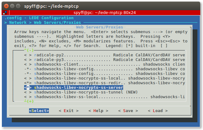
We can choose between the regular built in shadowsocks-libev components from original LEDE packages or my fork of shadowsocks-libev which is called shadowsocks-libev-nocrpyto where the encryption is optional (for turning off, choose none for cipher).
|
|
First, select the device (router) where You want to install LEDE as the target. For testing, use x86 and VirtualBox VDI image as output. Then navigate to Network > Web Servers/Proxies and select shadowsocks-libev-nocrypto-ss-local and shadowsocks-libev-nocrypto-ss-redir. Of course, You can select the regular versions from them without -nocrypto, but I recommend the nocrypto versions because of the better performance. Save the configuration!
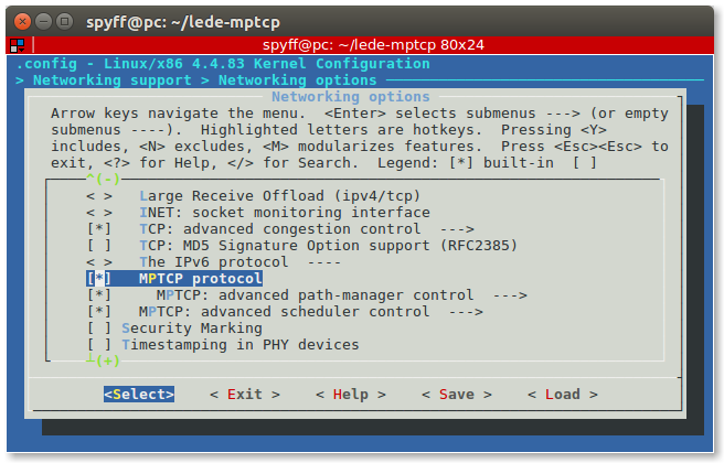
Next step we have to enable the MPTCP support in the kernel.
|
|
Then navigate into the Networking support > Networking options and enable MPTCP protocol. After that, go to the MPTCP: advanced path-manager submenu and select some path manager but at least one! It is very important to select at least one, otherwise the multipath just not work! Full-mesh path manager should be enough for normal use. Save the configuration!
We are ready with the configuration so let’s build the image!
|
|
After that, You should repeat the steps for another device. The output is a flashable image in every case, somewhere in the lede-mptcp/bin/targets and selected architecture folder. For flashing the images to the router You should find more information for searching the specific model. In most cases that is a simple firmware upgrade in the web admin GUI.
2. Assemble the physical test environment
-
For the tests, I use the following hardware:
- Netgear R7000 router
- Netgear R7800 router
- 2 Ubiquiti Loco M5 Wi-Fi bridges
- 2 Ubiquiti M5 Wi-Fi bridges
- Lots of small UTP cables
- A PC and a Laptop (or in some cases a RaspberryPi and a Laptop for the portable setup)
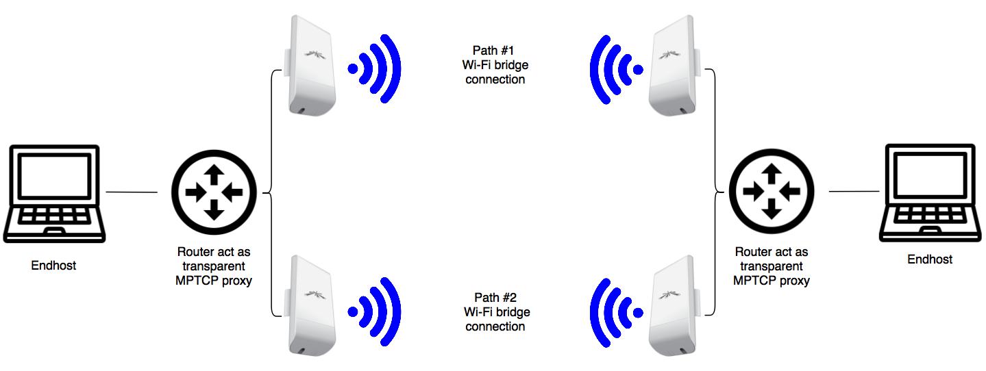
-
The schematic figure of my setup on the image above. We need 2 WAN connection and 1 LAN on every router. The most simple way if we are creating 3 VLANs. On these routers, there are 5 RJ-45 switch ports, I decided to put LAN to the original WAN port, WAN1 to port 1-2 and WAN2 to port 3-4.
-
Every Wi-Fi bridge is using DHCP to get the IP address. Path #1 bridges configured to use 5180 MHz frequency band, Path #2 bridges on 5700 MHz.
-
I put Path #1 bridges to WAN1 (connected to port 1 on each router) and Path #2 bridges to WAN2 (connected to port 3 on each router).
-
Client machines connected to the LAN port (which is the original yellow WAN port) on each router. They don’t need any config and get their IP addresses from the router LAN’s DHCP server.
-
WAN1 and WAN2 on the router which will run the ss-redir configured to get IP over DHCP. The router which runs the ss-server is configured with static IP and running a DHCP server.
-
Very simple adressing:
- LAN on R7000 router: 192.168.70.0/24
- LAN on R7800 router: 192.168.78.0/24
- WAN1 on each router: 10.1.1.0/24
- WAN2 on each router: 10.2.2.0/24
-
For the switch and network configuration I attached my examples which might be give some pointers even for different routers. Original and modified
etc/config/networkfiles included for both devices: R7000 original and modified file, R7800 original and modified file. For applying the modified configs You should SSH into the LEDE and type:
|
|
And paste the content of the new config. Then press Ctrl+D to close the file. For updating the old config:
|
|
Then reboot the router and You should see the new config running. Don’t forget to connect your cable into the new LAN port!
3. Apply the proxy configuration
Setup for proxy client:
SSH into the proxy-client device with the following command but replace the IP address with your router’s LAN IP (192.168.70.1 on R7000 and 192.168.78.1 on R7800 in my case). I used R7800 as the proxy client.
|
|
In the root prompt, check if ss-redir and ss-server are available.
|
|
This command maybe runs, maybe drops an error with invalid config path but in both cases is good for us. We create a config file for the ss-redir somewhere. In my case /etc/ss_redir.json which contains:
|
|
You can choose other ciphers as well instead of none. Check shadowsocks-libev manual on the web for all the available ciphers. I added both WAN IP address of the other router.
Then I opened up /etc/rc.local and added the following line before the exit 0 line, to start ss-redir when the router boots up:
|
|
For redirecting, all the TCP traffic to ss-redir, add another lines into the /etc/rc.local. The 4. line is because we don’t want to redirect traffic inside of the LAN.
|
|
The config for this router has done, reboot it.
Setup for proxy server: SSH into the another router which acts as a proxy server. In my case:
|
|
Then create a configuration file for the ss-server. For example /etc/ss_server.json:
|
|
Add the following line before the exit 0 into the /etc/rc.local to start ss-server on the router startup:
|
|
Thats it, reboot the router.
4. Verification of the MPTCP proxy operation
To try out if the testbed works well, just start an iperf3 measurement between the client machines. For example, in my case between the PC and the notebook:
|
|
on the PC which is connected to the R7800 LAN.
|
|
on the notebook which is connected to the R7000 LAN. The IP address there is my PC’s IP address. If everything works, You should see the sum of the two Wi-Fi bridges throughput. Check the video from my test environment below.
Summary
For more information from the project please check Freifunk blog posts linked below. This page is intended for my Google Summer of Code project summary page. My contributions:
- LEDE fork with MPTCP support, check the git diff which contains my modifications.
- shadowsocks-libev fork shadowsocks-libev-nocrpyto with optional cipher support. Check the git diff for my modifications.
- LEDE feed for my package(s).
- Blog posts on Freifunk blog.
- This manual with the configuration steps and examples.